Arduino: опять моргаем светодиодиками
Когда коту делать нечего, он известно чем занимается. А когда пенсионеру, тем более инвалиду делать нечего (что, в общем-то, его постоянное состояние), он ардуинит. Наверное. Вот и я решил опять поардуинить. Тряхнуть стариной и поморгать светодиодиком. Моргать одним светодиодом — как-то банально. Десяток — получше, но тоже пошловато. Будем моргать хотя бы тысячей — хотя это вопрос величины пенсии, можно и десять тысяч подключить, и намного больше.
Адресуемыми светодиодами моргать — это элементарно и каждый может. Ну и прожорливые они — самые распространенные WS812B изволят кушать 15 мА на цвет, если 1000 диодов включить на полную яркость — уже 45 ампер. Яркость для квартиры уже зашкалит. И всего 8 бит на цвет — оно вроде бы ничего при максимальной яркости, но когда её надо уменьшить, становится сильно мало. Но грешен, я этим баловался и уже неоднократно описывал такие моргалки:
- Raspbery Pi Pico для управления адресуемыми светодиодами
- Большой дисплей. Замороженный проект
- Делаем дисплей из адресуемых светодиодов
Посему делаем моргалку из сермяжных RGB светодиодов, самых дешевых, что можно найти — я нашел XL-B2020RGBA-HF за половину американского цента штука. Припаять столько светодиодов ручками — это для мазохистов. Пришлось разводить печатную плату и заказывать ее вместе с пайкой светодиодов. Со сборкой и пересылкой из jlcpcb.com мне это удовольствие вылилось в сумму около 43 баксов за 5 плат по 256 светодиодов, включая цену светодиодов.
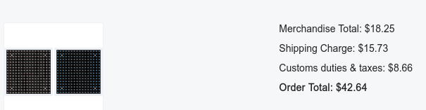
Честно говоря, это еще не все — я просто в то же время заказывал кое-какие детальки из lcsc.com, а они дают скидку на 15 долларов на доставку, если в это время вы заказываете плату со сборкой в jlcpcb.com — вот такая загогулина, экономика должна быть экономной, не правда ли дорогой Леонид Ильич?
В России такая халява сейчас не работает, будем надеяться, что временно.
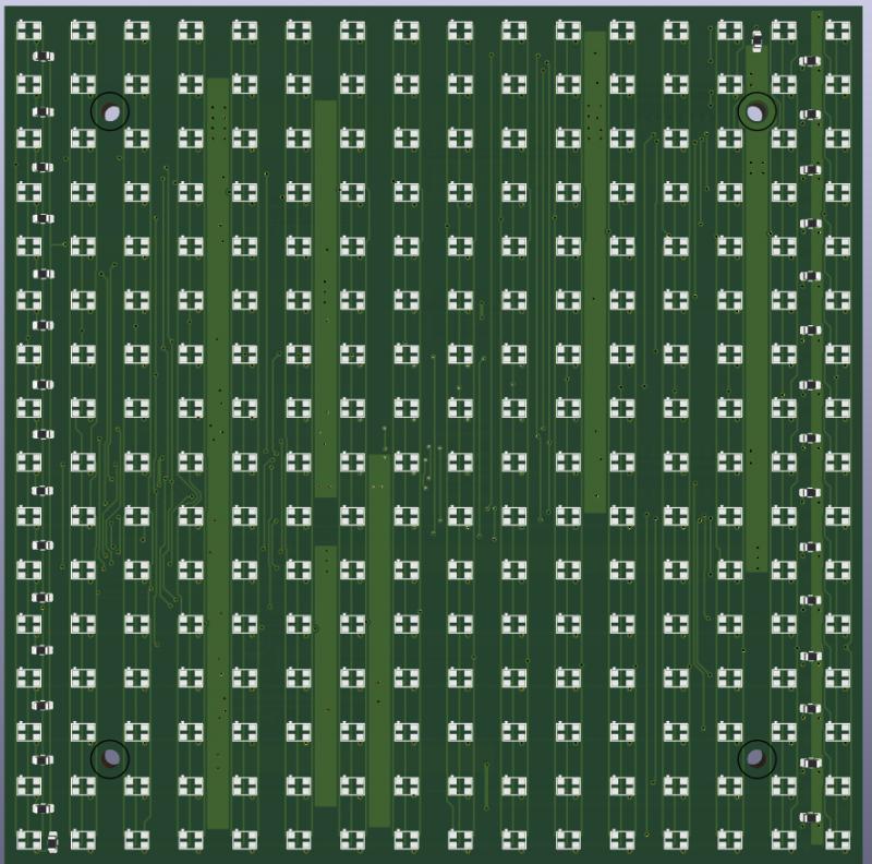
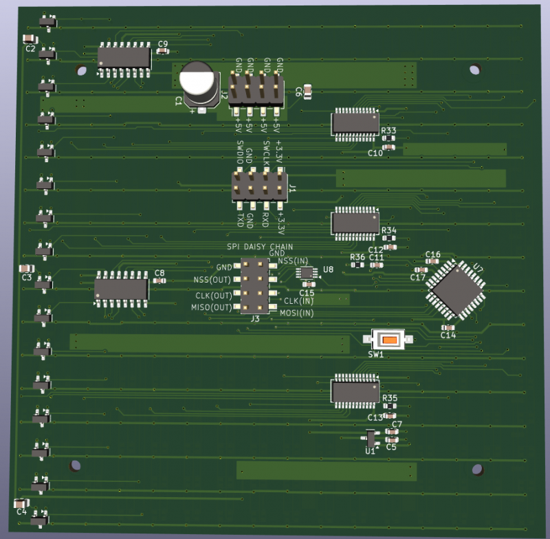
Получилось, что надо 4 платы с матрицей светодиодов 16х16, платы самые дешевые 10х10 сантиметров.
Разводить 256 светодиодов тоже задачка не для слабонервных, посему к Kicad подключаем Python и пишем небольшой скриптик, который расставит светодиоды и сделает всю регулярную разводку для нас. Скриптик я приведу. Он, конечно, малополезен без схемы, но если вы соберетесь писать свои скрипты, будет полезен в качестве примера. Тем более рабочие примеры и даже просто документацию найти крайне тяжело. Дело в том, что Kicad имеет библиотеку PCBNEW, но ее авторы мало заботятся о том, чтобы скрипты для старой версии работали в новой, и на описание для новых версий забили.
import pcbnew

panel_X_size = 100.0
panel_Y_size = 100.0

panel_rows = 16
panel_lines = 16
deltaX = panel_X_size/panel_rows
deltaY = panel_Y_size/panel_lines

panel_gap = 1
wire_gap = 0.7
origin=[0,0]

#pcb_name = 'RGB_matrix_orig.kicad_pcb'
pcb_name = 'RGB_matrix.kicad_pcb'
pcb_name2 = 'layout.kicad_pcb'


def Mount_placement(pcb):

    offset = 30.0

    hole = pcb.FindFootprintByReference("J1")
    hole.SetPosition(pcbnew.VECTOR2I_MM(-offset, offset))
    hole.Reference().SetVisible(False)

    hole = pcb.FindFootprintByReference("J2")
    hole.SetPosition(pcbnew.VECTOR2I_MM(offset, offset))
    hole.Reference().SetVisible(False)

    hole = pcb.FindFootprintByReference("J3")
    hole.SetPosition(pcbnew.VECTOR2I_MM(-offset, -offset))
    hole.Reference().SetVisible(False)

    hole = pcb.FindFootprintByReference("J4")
    hole.SetPosition(pcbnew.VECTOR2I_MM(offset, -offset))
    hole.Reference().SetVisible(False)

    hole = pcb.FindFootprintByReference("J5")
    hole.SetPosition(pcbnew.VECTOR2I_MM(0, offset))
    hole.Reference().SetVisible(False)

    hole = pcb.FindFootprintByReference("J6")
    hole.SetPosition(pcbnew.VECTOR2I_MM(0, -offset))
    hole.Reference().SetVisible(False)


    conn = pcb.FindFootprintByReference("J7")
    conn.SetPosition(pcbnew.VECTOR2I_MM(-(panel_Y_size/2-10.5), (panel_X_size/2-13.5)))
    conn.SetOrientation(pcbnew.EDA_ANGLE(-90, pcbnew.DEGREES_T))
    #conn.Flip(pcbnew.SIDE_BOTTOM)
    conn.Reference().SetVisible(False)

    conn = pcb.FindFootprintByReference("J8")
    conn.SetPosition(pcbnew.VECTOR2I_MM(-(panel_Y_size/2-10.5), -(panel_X_size/2-13.0)))
    conn.SetOrientation(pcbnew.EDA_ANGLE(-90, pcbnew.DEGREES_T))
    conn.Reference().SetVisible(False)

def LED_placement(pcb):
    for y in range (panel_lines):
        line_pos=[]
        for x in range (panel_rows):
            diode_ref =  y*panel_rows + x +1
            # Find the component
            c = pcb.FindFootprintByReference("LED"+str(diode_ref))
            # Place it somewhere
            pos = [0.0,0.0]
            rot =0
            pos[1]= origin[1] - (deltaY * (panel_lines-1))/2 + y*deltaY

            pos[0] = origin[0] - (deltaX * (panel_rows-1))/2 + x*deltaX
            rot = 0
            line_pos.append(pos)
            c.SetPosition(pcbnew.VECTOR2I_MM(pos[0], pos[1]))
            # Rotate it
            c.SetOrientation(pcbnew.EDA_ANGLE(rot, pcbnew.DEGREES_T))
            c.Reference().SetVisible(False)


def CAP_placement(pcb):
    for y in range (panel_lines):
        line_pos=[]
        for x in range (panel_rows):
            cap_ref =  y*panel_rows + x +1
            # Find the component
            c = pcb.FindFootprintByReference("C"+str(cap_ref))
            # Place it somewhere
            pos = [0.0,0.0]
            rot =0
            pos[1] = origin[1] + (deltaY * (panel_lines-1))/2 - y*deltaY
            if y%2==0:
                pos[0] = origin[0] - (deltaX * (panel_rows-1))/2 + x*deltaX
                pos[0] += 1.7
                pos[1] -= 4.3
                rot = 90 +180
            else:
                pos[0] = origin[0] + (deltaX * (panel_rows-1))/2 - x*deltaX
                pos[0] -= 1.7
                pos[1] += 4.3
                rot = 90
            line_pos.append(pos)
            c.SetPosition(pcbnew.VECTOR2I_MM(pos[0], pos[1]))
            # Rotate it
            c.SetOrientation(pcbnew.EDA_ANGLE(rot, pcbnew.DEGREES_T))
            c.Reference().SetVisible(False)
            c.Value().SetVisible(False)


def AddTrack(pcb, track, width, layer):
    for i in range (len(track)-1):
        t = pcbnew.PCB_TRACK(pcb)
        pcb.Add(t)
        t.SetStart(pcbnew.VECTOR2I(track[i][0], track[i][1]))
        t.SetEnd(pcbnew.VECTOR2I(track[i+1][0], track[i+1][1]))
        t.SetWidth(pcbnew.FromMM(width))
        #t.SetNetCode(netCode)
        t.SetLayer(layer)

def AddVia(pcb, pos, dia, drill):
    v = pcbnew.PCB_VIA(pcb)
    pcb.Add(v)
    v.SetViaType(pcbnew.VIATYPE_THROUGH)
    v.SetWidth(pcbnew.FromMM(dia))
    v.SetPosition(pcbnew.VECTOR2I(pos[0],pos[1]))
    #v.SetLayerPair(0,31)
    v.SetDrill(pcbnew.FromMM(drill))


def MOSFET_placement(pcb):
    for y in range (panel_lines):
            # Find the mosfet
            q = pcb.FindFootprintByReference("Q"+str(y+1))
            ledRef = "LED"+str((y+1)*panel_lines)
            led1 = pcb.FindFootprintByReference(ledRef)
            ledRef = "LED"+str((y+1)*panel_lines-1)
            led2 = pcb.FindFootprintByReference(ledRef)

            pos1 = led1.GetPosition()
            pos2 = led2.GetPosition()
            # Calculate the midpoint
            midpoint_x = (pos1.x + pos2.x) // 2
            midpoint_y = (pos1.y + pos2.y) // 2 + pcbnew.FromMM(0.5)
            q.SetPosition(pcbnew.VECTOR2I(midpoint_x, midpoint_y))
            q.SetOrientation(pcbnew.EDA_ANGLE(90, pcbnew.DEGREES_T))
            #q.SetLayer(pcbnew.B_Cu)

            q.Flip(q.GetPosition(),False)
            q.Reference().SetVisible(False)
            q.Value().SetVisible(False)

            track=[]
            for pad in q.Pads():
                if pad.GetPadName()=='3':
                    pad3_q = pad.GetPosition()
                    track.append(pad3_q)
                if pad.GetPadName()=='2':
                    pad2_q = pad.GetPosition()
                    vcc_track=[]
                    vcc_track.append(pad2_q)
                    vcc_viapoint  = [pad2_q.x, pad2_q.y - pcbnew.FromMM(1.2)]
                    vcc_track.append(vcc_viapoint)
                    AddTrack(pcb, vcc_track, 0.4, pcbnew.B_Cu)
                    AddVia(pcb, vcc_viapoint, 0.7, 0.3)

            for pad in led1.Pads():
                if pad.GetPadName()=='3':
                    pad3_led = pad.GetPosition()
                    viapoint = [pad3_q.x, pad3_led.y+ pcbnew.FromMM(wire_gap)]
                    track.append(viapoint)
                    AddTrack(pcb, track, 0.4, pcbnew.B_Cu)
                    #AddVia(pcb, viapoint, 0.7, 0.3)

def D74HC595_placement(pcb):
    chip1 = pcb.FindFootprintByReference("U4")
    chip2 = pcb.FindFootprintByReference("U5")
    ledRef = "LED"+str((1+1)*panel_lines-3)
    led = pcb.FindFootprintByReference(ledRef)
    for pad in led.Pads():
        if pad.GetPadName()=='3':
            pad3_led = pad.GetPosition()
            ref_point_x = pad3_led.x
            ref_point_y = pad3_led.y+pcbnew.FromMM(wire_gap)
            # U4
            chip1.SetPosition(pcbnew.VECTOR2I(ref_point_x , ref_point_y))
            chip1.SetOrientation(pcbnew.EDA_ANGLE(-90, pcbnew.DEGREES_T))
            chip1.Flip(chip1.GetPosition(),False)
            chip1.Reference().SetVisible(False)
            chip1.Value().SetVisible(False)
            # U5
            ref_point2_x = pad3_led.x
            ref_point2_y = pad3_led.y+pcbnew.FromMM(wire_gap+7*panel_Y_size/panel_lines)
            chip2.SetPosition(pcbnew.VECTOR2I(ref_point2_x , ref_point2_y))
            chip2.SetOrientation(pcbnew.EDA_ANGLE(-90, pcbnew.DEGREES_T))
            chip2.Flip(chip2.GetPosition(),False)
            chip2.Reference().SetVisible(False)
            chip2.Value().SetVisible(False)

    chip3 = pcb.FindFootprintByReference("U1")
    chip4 = pcb.FindFootprintByReference("U2")
    chip5 = pcb.FindFootprintByReference("U3")
    ledRef = "LED"+str((2+1)*panel_lines+6)
    led = pcb.FindFootprintByReference(ledRef)
    for pad in led.Pads():
        if pad.GetPadName()=='3':
            pad3_led = pad.GetPosition()
            ref_point_x = pad3_led.x
            ref_point_y = pad3_led.y+pcbnew.FromMM(wire_gap)
            # U1
            chip3.SetPosition(pcbnew.VECTOR2I(ref_point_x , ref_point_y))
            chip3.SetOrientation(pcbnew.EDA_ANGLE(90, pcbnew.DEGREES_T))
            chip3.Flip(chip3.GetPosition(),False)
            chip3.Reference().SetVisible(False)
            chip3.Value().SetVisible(False)
            # U2
            ref_point2_x = pad3_led.x
            ref_point2_y = pad3_led.y+pcbnew.FromMM(wire_gap+3*panel_Y_size/panel_lines)
            chip4.SetPosition(pcbnew.VECTOR2I(ref_point2_x , ref_point2_y))
            chip4.SetOrientation(pcbnew.EDA_ANGLE(-90, pcbnew.DEGREES_T))
            chip4.Flip(chip4.GetPosition(),False)
            chip4.Reference().SetVisible(False)
            chip4.Value().SetVisible(False)
            # U3
            ref_point2_x = pad3_led.x
            ref_point2_y = pad3_led.y+pcbnew.FromMM(wire_gap+8*panel_Y_size/panel_lines)
            chip5.SetPosition(pcbnew.VECTOR2I(ref_point2_x , ref_point2_y))
            chip5.SetOrientation(pcbnew.EDA_ANGLE(-90, pcbnew.DEGREES_T))
            chip5.Flip(chip5.GetPosition(),False)
            chip5.Reference().SetVisible(False)
            chip5.Value().SetVisible(False)


def CapGndLines(pcb):
    for y in range (panel_lines):
        for x in range (panel_rows):
            track=[]
            ref_num =  y*panel_rows + x +1
            led = pcb.FindFootprintByReference("LED"+str(ref_num))
            for pad in led.Pads():
                if pad.GetPadName()=='3':
                    #netCode = pad.GetNetCode
                    pos_x = pad.GetPosition().x
                    pos_y = pad.GetPosition().y
                    track.append([pos_x, pos_y])

            cap = pcb.FindFootprintByReference("C"+str(ref_num))
            for pad in cap.Pads():
                if pad.GetPadName()=='2':    #PIN2 GND
                    pos_x = pad.GetPosition().x
                    pos_y = pad.GetPosition().y
                    track.append([pos_x, pos_y])
                    #track.append([pos_x, pos_y+ pcbnew.PCB_IU_PER_MM(2)])
                    if y%2==0:
                        new_pos = [pos_x+pcbnew.FromMM(0.9), pos_y]
                        track.append(new_pos)
                        AddVia(pcb, new_pos, 0.7, 0.3)
                    else:
                        new_pos = [pos_x-pcbnew.FromMM(0.9), pos_y]
                        track.append(new_pos)
                        AddVia(pcb, new_pos, 0.7, 0.3)

            AddTrack(pcb, track, 0.25, 0)

def VerticalLines(pcb):
    track_pin1=[[] for _ in range (panel_rows)]
    track_pin2=[[] for _ in range (panel_rows)]
    track_pin4=[[] for _ in range (panel_rows)]
    track_pin3=[]

    for y in range (panel_lines):
        for x in range (panel_rows):
            ref_num =  y*panel_rows + x +1
            led = pcb.FindFootprintByReference("LED"+str(ref_num))
            for pad in led.Pads():
                track=[]
                if pad.GetPadName()=='1':
                    pos_x = pad.GetPosition().x
                    pos_y = pad.GetPosition().y
                    track.append([pos_x, pos_y])
                    new_pos = [pos_x-pcbnew.FromMM(wire_gap), pos_y]
                    track.append(new_pos)
                    track_pin1[x].append(new_pos)
                if pad.GetPadName()=='4':
                    pos_x = pad.GetPosition().x
                    pos_y = pad.GetPosition().y
                    track.append([pos_x, pos_y])
                    new_pos = [pos_x+pcbnew.FromMM(wire_gap), pos_y]
                    track.append(new_pos)
                    track_pin4[x].append(new_pos)
                if pad.GetPadName()=='2':
                    pos_x = pad.GetPosition().x
                    pos_y = pad.GetPosition().y
                    track.append([pos_x, pos_y])
                    new_pos = [pos_x+pcbnew.FromMM(wire_gap), pos_y]
                    track.append(new_pos)
                    track_pin2[x].append(new_pos)
                if pad.GetPadName()=='3':
                    pos_x = pad.GetPosition().x
                    pos_y = pad.GetPosition().y
                    track.append([pos_x, pos_y])
                    new_pos = [pos_x, pos_y+pcbnew.FromMM(wire_gap)]
                    track.append(new_pos)
                    AddVia(pcb, new_pos, 0.7, 0.3)
                    track_pin3.append(new_pos)


                AddTrack(pcb, track, 0.2, pcbnew.F_Cu)
        AddTrack(pcb, track_pin3, 0.4, pcbnew.B_Cu)
        track_pin3=[]

#    for trackX in track_pin1[:-1]:
    for trackX in track_pin1:
        AddTrack(pcb, trackX, 0.2, pcbnew.F_Cu)
    for trackX in track_pin2:
        AddTrack(pcb, trackX, 0.2, pcbnew.F_Cu)
    for trackX in track_pin4:
        AddTrack(pcb, trackX, 0.2, pcbnew.F_Cu)

#    print(track_pin1[0])

def DataLines(pcb):
    bottom_track1=[]
    bottom_track2=[]
    track_counter=0
    cross_wire = False
    for y in range (panel_lines):
        for x in range (panel_rows):
            track=[]
            ref_num =  y*panel_rows + x +1
            led = pcb.FindFootprintByReference("LED"+str(ref_num))
            for pad in led.Pads():
                if pad.GetPadName()=='2':  # output
                    pos_x = pad.GetPosition().x
                    pos_y = pad.GetPosition().y
                    track.append([pos_x, pos_y])

                    if y%2==0:
                        new_pos = [pos_x+pcbnew.FromMM(1.2), pos_y]
                    else:
                        new_pos = [pos_x-pcbnew.FromMM(1.2), pos_y]
                    track.append(new_pos)


                    if ((x==(panel_rows-1))  and (y%2 != 0)):
                        new_pos[0] -= pcbnew.FromMM(0.3)
                    elif ((x==(panel_rows-1))  and (y%2 == 0)):
                        new_pos[0] += pcbnew.FromMM(0.5)
                    else:
                        AddVia(pcb, new_pos, 0.7, 0.3)
                    AddTrack(pcb, track, 0.25, 0)

                    if track_counter == 0:
                        bottom_track1.append(new_pos)
                    else:
                        bottom_track2.append(new_pos)

                track=[]
                if pad.GetPadName()=='4':  # input
                    pos_x = pad.GetPosition().x
                    pos_y = pad.GetPosition().y
                    track.append([pos_x, pos_y])

                    if y%2==0:
                        new_pos = [pos_x-pcbnew.FromMM(1.2), pos_y]
                    else:
                        new_pos = [pos_x+pcbnew.FromMM(1.2), pos_y]
                    track.append(new_pos)


                    if ((x==0) and (y%2==0)):
                        new_pos[0] -= pcbnew.FromMM(0.3)
                        cross_wire = True
                    elif ((x==0) and (y%2!=0)):
                        new_pos[0] += pcbnew.FromMM(0.5)
                        cross_wire = True
                    else:
                        AddVia(pcb, new_pos, 0.7, 0.3)
                    AddTrack(pcb, track, 0.25, 0)


                    if track_counter == 0:
                        bottom_track2.append(new_pos)
                        track_counter=1
                    else:
                        bottom_track1.append(new_pos)
                        track_counter=0

            layer=31
            if cross_wire:
                cross_wire = False
                layer = 0


            if track_counter == 0:
                AddTrack(pcb, bottom_track1, 0.25, layer)
                bottom_track1=[]

            else:
                AddTrack(pcb, bottom_track2, 0.25, layer)
                bottom_track2=[]


def DrawPolygons(pcb):

    plane_size=[0,0]
    plane_size[0]= panel_X_size/2 - panel_gap/4 - 0.2
    plane_size[1]= panel_Y_size/2 - panel_gap/4 - 0.2
    points = [
        (  plane_size[0],  plane_size[1]),
        ( -plane_size[0],  plane_size[1]),
        ( -plane_size[0], -plane_size[1]),
        (  plane_size[0], -plane_size[1])
    ]

    points = [(pcbnew.FromMM(x), pcbnew.FromMM(y)) for (x,y) in points]

    chain = pcbnew.SHAPE_LINE_CHAIN()

    for (x,y) in points:
        chain.Append(x, y)
    chain.SetClosed(True)

    zone = pcbnew.ZONE(pcb)
    zone.SetLayer(pcbnew.B_Cu)
    zone.AddPolygon(pcbnew.SHAPE_LINE_CHAIN(chain))
    net_pwr = pcb.FindNet("GND")
    zone.SetNet(net_pwr)
    zone.SetThermalReliefGap(pcbnew.FromMM(0.25))
    zone.SetThermalReliefSpokeWidth(pcbnew.FromMM(0.5))
    zone.SetLocalClearance(pcbnew.FromMM(0.25))
    pcb.Add(zone)

    zone = pcbnew.ZONE(pcb)
    zone.SetLayer(pcbnew.F_Cu)
    zone.AddPolygon(pcbnew.SHAPE_LINE_CHAIN(chain))
    net_pwr = pcb.FindNet("+5V")
    zone.SetThermalReliefGap(pcbnew.FromMM(0.25))
    zone.SetThermalReliefSpokeWidth(pcbnew.FromMM(0.5))
    zone.SetLocalClearance(pcbnew.FromMM(0.25))
    zone.SetNet(net_pwr)
    pcb.Add(zone)


def DrawEdges(pcb):
    plane_size=[0,0]
    plane_size[0]= panel_X_size/2 - panel_gap/4
    plane_size[1]= panel_Y_size/2 - panel_gap/4
    points = [
        (  plane_size[0],  plane_size[1]),
        ( -plane_size[0], -plane_size[1])
    ]
    points = [(pcbnew.FromMM(x), pcbnew.FromMM(y)) for (x,y) in points]
    points = [(int(x), int(y)) for (x,y) in points]

    pcb_shape = pcbnew.PCB_SHAPE(pcb)
    pcb_shape.SetLayer(pcbnew.Edge_Cuts)
    pcb_shape.SetShape(pcbnew.SHAPE_T_RECT)
    pcb_shape.SetStart(pcbnew.VECTOR2I(points[0][0], points[0][1]))
    pcb_shape.SetEnd(pcbnew.VECTOR2I(points[1][0], points[1][1]))
    pcb.Add(pcb_shape)


def Convert():
    print("start")
    pcb = pcbnew.LoadBoard(pcb_name)
    DrawEdges(pcb)
    LED_placement(pcb)
    VerticalLines(pcb)
    MOSFET_placement(pcb)
    D74HC595_placement(pcb)
    #CAP_placement(pcb)
    #CapGndLines(pcb)
    #DataLines(pcb)
    #Mount_placement(pcb)
    #DrawPolygons(pcb)
    pcb.Save(pcb_name2)

    print("created!")

Convert()
Несколько лет назад я описывал разработку аналогичного скрипта, но с нынешней версией Kicad это уже не работает — Разводка регулярных структур в KiCAD: путь лентяя
Теперь выбираем микросхемы для управления матрицей. Для управления линией удобно использовать специальные драйверы тока для светодиодов, у них как раз 16 выходов. На каждый цвет по одному драйверу — на плату их надо 3 штуки. Купить нужные оказалось не сложно, а очень сложно. Их выпускается просто тьма, в основном китайские, но с документацией большая проблема. В спецификации только подключение, основные параметры и картинка корпуса микросхемы. О программировании — ни слова. Где-то в интернетах я нашел статью одного товарища (тамбовский волк после этого ему товарищ), который писал, что микросхемы ICND2153, которые я нашел дешево на Али, являются полной копией STP1612PW05, которые за разумные деньги не купишь, но на них имеется достаточно хорошая спецификация. Когда я начал пытаться программировать, выяснилось, что товарищ несколько соврамши.
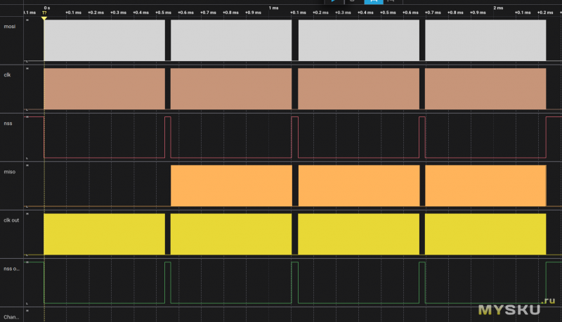
К счастью, нашлась картинка с анализом осциллограмм для микросхем ICND2153 от другого товарища, которому в руки попала готовая светодиодная матрица с такими микросхемами, и он проанализировал интерфейс.
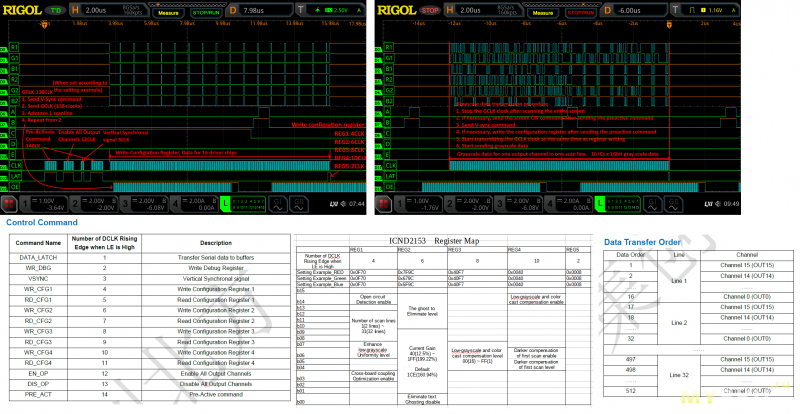
Не все, что он изложил — правда, но мне этого хватило, после дня экспериментов микросхема худо-бедно задышала. Все, что удалось выяснить, я оформил, как дополнение к отсутствующей части спецификации, и выложил здесь. Извините, на англицком. Начало оригинальной спецификации тоже на всякий сохранено здесь.
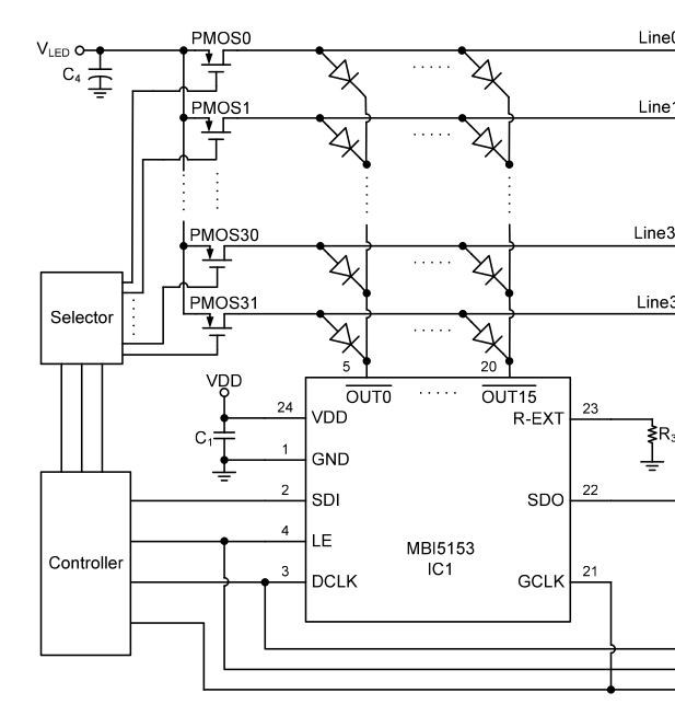
С переключением колонок проблем меньше, но они есть. Каждая колонка — это 48 светодиодов, ток нужно обеспечить около ампера. Управляются они дешифратором или сдвиговым регистром. Я микросхем с таким выходным током не нашел, хотя они точно есть и используются в светодиодных панелях. Я в итоге поставил банальные 8-разрядные сдвиговые регистры 74HC595 в количестве двух штук с p-MOSFET транзисторами на выходах. 16 транзисторов пляж точно не украшают, но что делать? Кому сейчас легко?
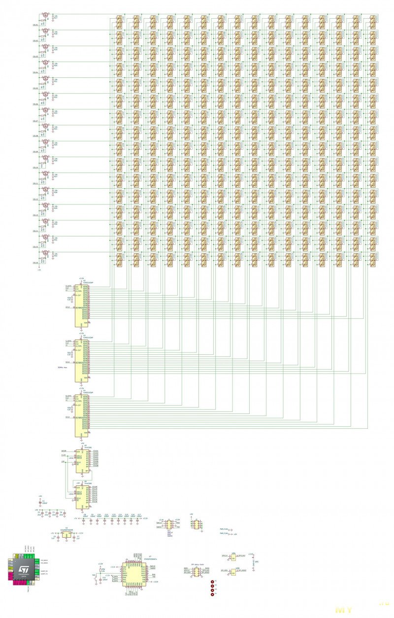
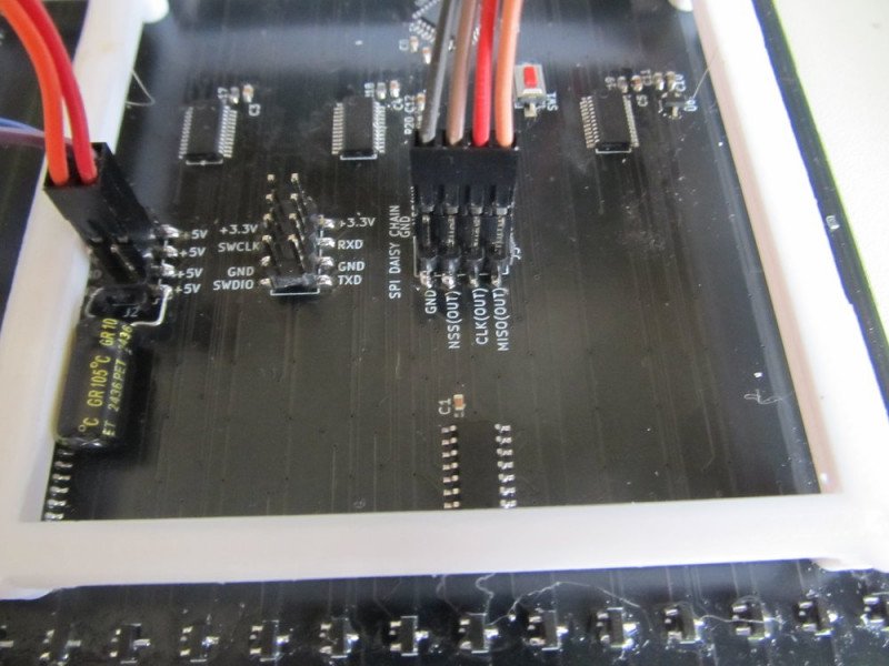
Выбор микроконтроллера управления панелью вылился в отдельный квест. На плате двухсторонний монтаж компонентов, плата двухсторонняя и везде сплошные трассы. Нужен корпус, который можно установить так, чтобы он не мешал трассировке — лучше всего с выводами по двум сторонам. В самом крайнем случае, LQFP-32 с шагом 0.8мм с трудом можно развести. Из дополнительных требование — мне нужен DMA с доступом как минимум 8 ног и SPI. Вроде бы требования почти никакие, но найти удалось всего ничего.
Сначала было польстился на STM32G030K8T6 — LQFP-32 64 Kbytes Flash 8 Kbytes RAM, все порты, все понты, и очень дешевый. Начал экспериментировать с макеткой — и выяснилась одна неприятная для меня мелочь. Серия STM32G030 не умеет дергать лапами через DMA. Это вроде как такое усовершенствование — процессор теперь может лапками перебирать быстрее, но связь с DMA пропала.
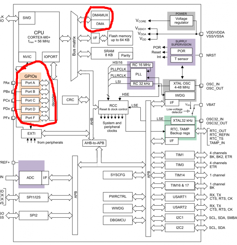
Печалька. Пришлось довольствоваться STM32F030K6T6, у него всего 32 Kbytes Flash и 4K Kbytes RAM — маловато будет, но мы, бояре, народ работящий — как-нибудь выкрутимся.
Реализуем что-то напоминающее SPI Daisy Chain — только там по цепочке передается каждый байт, а здесь — блок. Т.е. первая панель принимает от мастера 4 блока, а дальше отправляется первый — пустой, а остальные сдвигом на блок. После завершения передачи — если в течении 2 миллисекунд нет новых блоков, все панели одновременно отображают последний полученный блок.
В общем, поведение напоминает WS812B. Данные для 4 панелей передаются за 2.24 миллисекунд — такой скорости хватит, чтобы демонстрировать видео на 40 панелях. Есть и табличная гамма-коррекция — исходно имеем 8 бит на цвет, реально мы можем отображать 16 бит на цвет, что и используем для коррекции.
Как сделать табличную гамма-коррекцию — без Питона никуда.
f = open("LUT.h", "w+")
f.write("// LUT converter gamut & 8bits to 16/12")
f.write("const uint16_t gammaLUT[256] = {\n")
lineCounter= 16
gamma = 2.2
for i in range(256):
    value = pow(i/ 255.0, gamma) *  65535.0     #4095.0

    f.write(str(int(round(value,0)))+', ')
    lineCounter -= 1
    if (lineCounter==0):
        f.write("\n")
        lineCounter =16

f.close()
Процессор пришлось чуть разогнать — 64МГц вместо положенных 48, быстродействия не хватало, время от времени были непонятные моргания. Но какой же ты пионер без ножа? (Вот тебе 100 грамм и пончик.)
#include "stm32f0xx.h"
#define WIDTH 16
#define HEIGHT 16
#define PACKET_SIZE (WIDTH * HEIGHT * 3)
uint8_t target_buffer[PACKET_SIZE] __attribute__((aligned(4)));
uint8_t buffer[PACKET_SIZE] __attribute__((aligned(4)));
volatile bool dma_transfer_complete = false;
#define DMA_BUFF_LEN 70
uint8_t DmaBuffer[DMA_BUFF_LEN];
bool dma_gpio_complete = false;
bool buff_ready = false;
#include "spi_chain.h"
#include "dma_portA.h"
const uint16_t gammaLUT[256] __attribute__((section(".rodata"))) = {
0, 0, 2, 4, 7, 11, 17, 24, 32, 42, 53, 65, 79, 94, 111, 129,
148, 169, 192, 216, 242, 270, 299, 330, 362, 396, 432, 469, 508, 549, 591, 635,
681, 729, 779, 830, 883, 938, 995, 1053, 1113, 1175, 1239, 1305, 1373, 1443, 1514, 1587,
1663, 1740, 1819, 1900, 1983, 2068, 2155, 2243, 2334, 2427, 2521, 2618, 2717, 2817, 2920, 3024,
3131, 3240, 3350, 3463, 3578, 3694, 3813, 3934, 4057, 4182, 4309, 4438, 4570, 4703, 4838, 4976,
5115, 5257, 5401, 5547, 5695, 5845, 5998, 6152, 6309, 6468, 6629, 6792, 6957, 7124, 7294, 7466,
7640, 7816, 7994, 8175, 8358, 8543, 8730, 8919, 9111, 9305, 9501, 9699, 9900, 10102, 10307, 10515,
10724, 10936, 11150, 11366, 11585, 11806, 12029, 12254, 12482, 12712, 12944, 13179, 13416, 13655, 13896, 14140,
14386, 14635, 14885, 15138, 15394, 15652, 15912, 16174, 16439, 16706, 16975, 17247, 17521, 17798, 18077, 18358,
18642, 18928, 19216, 19507, 19800, 20095, 20393, 20694, 20996, 21301, 21609, 21919, 22231, 22546, 22863, 23182,
23504, 23829, 24156, 24485, 24817, 25151, 25487, 25826, 26168, 26512, 26858, 27207, 27558, 27912, 28268, 28627,
28988, 29351, 29717, 30086, 30457, 30830, 31206, 31585, 31966, 32349, 32735, 33124, 33514, 33908, 34304, 34702,
35103, 35507, 35913, 36321, 36732, 37146, 37562, 37981, 38402, 38825, 39252, 39680, 40112, 40546, 40982, 41421,
41862, 42306, 42753, 43202, 43654, 44108, 44565, 45025, 45487, 45951, 46418, 46888, 47360, 47835, 48313, 48793,
49275, 49761, 50249, 50739, 51232, 51728, 52226, 52727, 53230, 53736, 54245, 54756, 55270, 55787, 56306, 56828,
57352, 57879, 58409, 58941, 59476, 60014, 60554, 61097, 61642, 62190, 62741, 63295, 63851, 64410, 64971, 65535,
};
const uint8_t wave_table[16] __attribute__((section(".rodata"))) = {0, 50, 100, 142, 181, 212, 231, 242, 231, 212, 181, 142, 100, 50, 0, 0};
void fill_gradient_buffer()
{
for (int y = 0; y < HEIGHT; y++)
{
for (int x = 0; x < WIDTH; x++)
{
int index = (y * WIDTH + x) * 3;
uint8_t t = ((x + y) * 16) / (WIDTH + HEIGHT);
uint8_t idx = t & 15;
target_buffer[index + 0] = wave_table[idx];
target_buffer[index + 1] = wave_table[(idx + 5) & 15];
target_buffer[index + 2] = wave_table[(idx + 10) & 15];
}
}
}
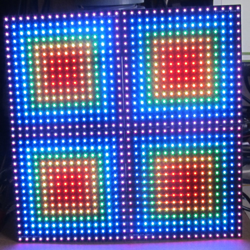
void fill_squares_buffer()
{
const uint8_t rainbow[7][3] = {
{255, 0, 0},
{255, 165, 0},
{255, 255, 0},
{0, 255, 0},
{0, 255, 255},
{0, 0, 255},
{128, 0, 128}};
for (uint8_t y = 0; y < HEIGHT; y++)
{
for (uint8_t x = 0; x < WIDTH; x++)
{
uint16_t index = (y * WIDTH + x) * 3;
if ((x == 7 || x == 8) && (y == 7 || y == 8))
{
target_buffer[index + 0] = 255;
target_buffer[index + 1] = 0;
target_buffer[index + 2] = 0;
}
else
{
int8_t dx = (x < 8) ? (7 - x) : (x - 8);
int8_t dy = (y < 8) ? (7 - y) : (y - 8);
uint8_t dist = (dx > dy) ? dx : dy;
uint8_t color = (dist - 1) % 7;
target_buffer[index + 0] = rainbow[color][0];
target_buffer[index + 1] = rainbow[color][1];
target_buffer[index + 2] = rainbow[color][2];
}
}
}
}
void fill_color(uint8_t color)
{
for (uint8_t y = 0; y < HEIGHT; y++)
{
for (uint8_t x = 0; x < WIDTH; x++)
{
uint16_t index = (y * WIDTH + x) * 3;
target_buffer[index + 0] = 0;
target_buffer[index + 1] = 0;
target_buffer[index + 2] = 0;
if (color == 0)
target_buffer[index + 0] = 255;
else if (color == 1)
target_buffer[index + 1] = 255;
else if (color == 2)
target_buffer[index + 2] = 255;
}
}
}
void fill_arrows()
{
memset(target_buffer, 0, PACKET_SIZE);
for (uint8_t y = 0; y < HEIGHT; y++)
{
for (uint8_t x = 0; x < WIDTH; x++)
{
uint16_t index = (y * WIDTH + x) * 3;
uint8_t r = 0, g = 0, b = 0;
if (y < 10 && x >= 6 && x >= 6 + y)
r = 255;
else if (x < 10 && y >= 6 && y >= 6 + x)
g = 255;
target_buffer[index + 0] = r;
target_buffer[index + 1] = g;
target_buffer[index + 2] = b;
}
}
}
void pre_activ()
{
memset(DmaBuffer, 0x80, 32);
uint8_t dma_buf_ptr = 1;
DmaBuffer[dma_buf_ptr++] |= 0x10;
for (uint8_t i = 0; i < 14; i++)
{
DmaBuffer[dma_buf_ptr++] |= 0x10;
DmaBuffer[dma_buf_ptr++] |= 0x10 | 0x08;
}
DmaBuffer[dma_buf_ptr++] |= 0x10;
while (!dma_gpio_complete);
DMA1_Channel4->CNDTR = 32;
DMA1_Channel4->CCR |= DMA_CCR_EN;
dma_gpio_complete = false;
}
void outs_en()
{
memset(DmaBuffer, 0x80, 28);
uint8_t dma_buf_ptr = 1;
DmaBuffer[dma_buf_ptr++] |= 0x10;
for (uint8_t i = 0; i < 12; i++)
{
DmaBuffer[dma_buf_ptr++] |= 0x10;
DmaBuffer[dma_buf_ptr++] |= 0x10 | 0x08;
}
DmaBuffer[dma_buf_ptr++] |= 0x10;
while (!dma_gpio_complete);
DMA1_Channel4->CNDTR = 28;
DMA1_Channel4->CCR |= DMA_CCR_EN;
dma_gpio_complete = false;
}
void vsync()
{
memset(DmaBuffer, 0x80, 10);
uint8_t dma_buf_ptr = 1;
DmaBuffer[dma_buf_ptr++] |= 0x10;
for (uint8_t i = 0; i < 3; i++)
{
DmaBuffer[dma_buf_ptr++] |= 0x10;
DmaBuffer[dma_buf_ptr++] |= 0x10 | 0x08;
}
DmaBuffer[dma_buf_ptr++] |= 0x10;
while (!dma_gpio_complete);
DMA1_Channel4->CNDTR = 10;
DMA1_Channel4->CCR |= DMA_CCR_EN;
dma_gpio_complete = false;
}
void SRAM_wr()
{
memset(DmaBuffer, 0x80, 10);
uint8_t dma_buf_ptr = 1;
DmaBuffer[dma_buf_ptr++] |= 0x10;
DmaBuffer[dma_buf_ptr++] |= 0x10;
DmaBuffer[dma_buf_ptr++] |= 0x10 | 0x08;
DmaBuffer[dma_buf_ptr++] |= 0x10;
while (!dma_gpio_complete);
DMA1_Channel4->CNDTR = 10;
DMA1_Channel4->CCR |= DMA_CCR_EN;
dma_gpio_complete = false;
}
void reg_ctrl(uint16_t ctrl_data, uint8_t LEs)
{
memset(DmaBuffer, 0x80, DMA_BUFF_LEN);
uint16_t RGBgamma[3] = {ctrl_data, ctrl_data, ctrl_data};
uint8_t highBytes[8] = {0};
uint8_t lowBytes[8] = {0};
for (uint8_t i = 0; i < 3; i++)
{
highBytes[i] = RGBgamma[i] >> 8;
lowBytes[i] = RGBgamma[i];
}
uint8_t dma_buf_ptr = 1;
uint16_t mask = 0x8000;
for (uint8_t i = 0; i < 16; i++)
{
uint8_t datamask = 0;
uint8_t data_byte = 0;
if (RGBgamma[0] & mask)
datamask |= 0x01;
if (RGBgamma[1] & mask)
datamask |= 0x02;
if (RGBgamma[2] & mask)
datamask |= 0x04;
data_byte |= datamask;
mask >>= 1;
if (i > (15 - LEs))
data_byte |= 0x10;
DmaBuffer[dma_buf_ptr++] |= data_byte;
data_byte |= 0x08 | datamask;
if (i > (15 - LEs))
data_byte |= 0x10;
DmaBuffer[dma_buf_ptr++] |= data_byte;
}
while (!dma_gpio_complete);
DMA1_Channel4->CCR |= DMA_CCR_EN;
dma_gpio_complete = false;
}
void mosfet_switch(uint8_t row)
{
memset(DmaBuffer, 0x80, DMA_BUFF_LEN);
memset(DmaBuffer + 1, 0, 65);
DmaBuffer[33] = 0x80;
uint8_t *buf = DmaBuffer + 1;
for (uint8_t i = 0; i < 16; i++)
{
*buf++ |= 0x20;
*buf++ |= 0x60;
}
buf++;
for (uint8_t i = 0; i < 16; i++)
{
uint8_t data_byte = (i == row) ? 0x00 : 0x20;
*buf++ |= data_byte;
*buf++ |= (data_byte | 0x40);
}
while (!dma_gpio_complete);
DMA1_Channel4->CNDTR = DMA_BUFF_LEN;
DMA1_Channel4->CCR |= DMA_CCR_EN;
dma_gpio_complete = false;
}
void fill_buff(uint8_t *buf_pnt, uint8_t word_cnt, uint8_t row)
{
row &= 0x0F;
buf_pnt += (row * 16 + word_cnt) * 3;
uint16_t RGBgamma[3];
for (uint8_t i = 0; i < 3; i++)
RGBgamma[i] = gammaLUT[*buf_pnt++];
uint8_t highBytes[8] = {0};
uint8_t lowBytes[8] = {0};
for (uint8_t i = 0; i < 3; i++)
{
highBytes[i] = RGBgamma[i] >> 8;
lowBytes[i] = RGBgamma[i];
}
memset(DmaBuffer, 0x80, DMA_BUFF_LEN);
uint8_t dma_buf_ptr = 1;
uint16_t mask = 0x8000;
for (uint8_t i = 0; i < 16; i++)
{
uint8_t datamask = 0;
uint8_t data_byte = 0;
if (RGBgamma[0] & mask)
datamask |= 0x01;
if (RGBgamma[1] & mask)
datamask |= 0x02;
if (RGBgamma[2] & mask)
datamask |= 0x04;
data_byte |= datamask;
mask >>= 1;
if (i > 14)
data_byte |= 0x10;
DmaBuffer[dma_buf_ptr++] |= data_byte;
data_byte |= 0x08 | datamask;
if (i > 14)
data_byte |= 0x10;
DmaBuffer[dma_buf_ptr++] |= data_byte;
}
while (!dma_gpio_complete);
DMA1_Channel4->CNDTR = DMA_BUFF_LEN;
DMA1_Channel4->CCR |= DMA_CCR_EN;
dma_gpio_complete = false;
}
void tim17_setup()
{
RCC->APB2ENR |= RCC_APB2ENR_TIM17EN;
TIM17->PSC = 48 - 1;
TIM17->ARR = 833 - 1;
TIM17->DIER |= TIM_DIER_UIE;
TIM17->CR1 |= TIM_CR1_CEN;
NVIC_SetPriority(TIM17_IRQn, 1);
NVIC_EnableIRQ(TIM17_IRQn);
}
bool time_to_go = false;
extern "C" void TIM17_IRQHandler()
{
if (TIM17->SR & TIM_SR_UIF)
{
TIM17->SR &= ~TIM_SR_UIF;
time_to_go = true;
}
}
void system_clock_config()
{
RCC->CR &= ~RCC_CR_PLLON;
RCC->CFGR = 0;
RCC->CR |= RCC_CR_HSION;
while (!(RCC->CR & RCC_CR_HSIRDY));
FLASH->ACR |= FLASH_ACR_PRFTBE;
FLASH->ACR &= ~FLASH_ACR_LATENCY;
FLASH->ACR |= 0x2;
RCC->CFGR = RCC_CFGR_PLLMUL16 | RCC_CFGR_PLLSRC_HSI_DIV2;
RCC->CR |= RCC_CR_PLLON;
while (!(RCC->CR & RCC_CR_PLLRDY));
RCC->CFGR |= RCC_CFGR_SW_PLL;
while ((RCC->CFGR & RCC_CFGR_SWS) != RCC_CFGR_SWS_PLL);
}
void setup()
{
system_clock_config();
fill_squares_buffer();
tim3_setup();
dma_port_setup();
spi_chain_setup();
tim17_setup();
dma_gpio_complete = true;
pre_activ();
outs_en();
pre_activ();
vsync();
pre_activ();
reg_ctrl(0x0070, 4);
pre_activ();
reg_ctrl(0x7F9C, 6);
pre_activ();
reg_ctrl(0x40F7, 8);
pre_activ();
reg_ctrl(0x0040, 10);
pre_activ();
reg_ctrl(0x0008, 2);
}
void loop()
{
uint8_t *pointer = target_buffer;
static uint8_t row = 0;
if (time_to_go)
{
time_to_go = false;
for (uint8_t i = 0; i < 16; i++)
fill_buff(pointer, i, row);
pre_activ();
vsync();
TIM3->CCER &= ~TIM_CCER_CC3E;
mosfet_switch(row);
delayMicroseconds(8);
TIM3->CCER |= TIM_CCER_CC3E;
row++;
row &= 0x0F;
}
if (buff_ready)
{
DMA1_Channel5->CCR |= DMA_CCR_EN;
buff_ready = false;
}
}#ifndef _DMA_PORTA_H
#define _DMA_PORTA_H
// DMA conflict!!! p152
void tim16_setup()
{
RCC->APB2ENR |= RCC_APB2ENR_TIM16EN;
TIM16->ARR = 1;
TIM16->DIER |= TIM_DIER_UDE; // Update DMA request enable
TIM16->CR2 |= TIM_CR2_MMS_1; // TRGO selection: update event
TIM16->CR1 |= TIM_CR1_CEN; // Enable Timer 16
SYSCFG->CFGR1 |= SYSCFG_CFGR1_TIM16_DMA_RMP; // remap TIM16 to DMA ch4
}
void dma_setup()
{
// Enable clocks for GPIOA and DMA1
RCC->AHBENR |= RCC_AHBENR_GPIOAEN | RCC_AHBENR_DMA1EN;
// Configure GPIOA as output
GPIOA->MODER &= 0xFFFF0000;
GPIOA->MODER |= 0x00005555;
GPIOA->OSPEEDR |= 0x0000FFFF;
// Configure DMA
DMA1_Channel4->CCR = 0;
DMA1_Channel4->CPAR = (uint32_t)&GPIOA->ODR; // Peripheral address (GPIOA ODR)
DMA1_Channel4->CMAR = (uint32_t)DmaBuffer; // Memory address (DmaBuffer)
DMA1_Channel4->CNDTR = sizeof(DmaBuffer); // Number of data items
// Memory increment, Memory to peripheral, Transfer complete interrupt
DMA1_Channel4->CCR = DMA_CCR_PL_0 | DMA_CCR_PL_1 | DMA_CCR_MINC | DMA_CCR_DIR | DMA_CCR_TCIE | DMA_CCR_EN;
NVIC_EnableIRQ(DMA1_Channel4_5_IRQn); // Enable DMA1 Channel 3 interrupt
}
extern "C" void DMA1_Channel4_5_IRQHandler()
{
if (DMA1->ISR & DMA_ISR_TCIF4)
{
DMA1->IFCR |= DMA_IFCR_CTCIF4; // Clear transfer complete flag
DMA1_Channel4->CCR &= ~DMA_CCR_EN;
DMA1_Channel4->CNDTR = sizeof(DmaBuffer); // Reload DMA for the next transfer
dma_gpio_complete = true;
}
if (DMA1->ISR & DMA_ISR_TCIF5)
{
DMA1->IFCR |= DMA_IFCR_CTCIF5; // Clear the Transfer Complete (TC) flag
DMA1_Channel5->CCR &= ~DMA_CCR_EN;
DMA1_Channel5->CNDTR = PACKET_SIZE / 4; // Reset the number of data to transfer
dma_transfer_complete = true;
GPIOB->ODR &= ~0x40;
}
}
void tim3_setup()
{
// Enable the clock for GPIOB
RCC->AHBENR |= RCC_AHBENR_GPIOBEN;
// Enable the clock for Timer 3
RCC->APB1ENR |= RCC_APB1ENR_TIM3EN;
// Set PB0 to alternate function mode
GPIOB->MODER &= ~(GPIO_MODER_MODER0); // Clear mode
GPIOB->MODER |= GPIO_MODER_MODER0_1; // Set to alternate function mode
// Set the alternate function for PB0 to AF1 (TIM3_CH3)
GPIOB->AFR[0] &= ~(GPIO_AFRL_AFRL0); // Clear AF
GPIOB->AFR[0] |= 1 << (0 * 4); // Set to AF1
// Configure Timer 3
TIM3->CR1 = 0; // Clear control register 1
TIM3->PSC = 0; // No prescaler, timer clock = system clock
//TIM3->ARR = 1; // Auto-reload register value (to get 24 MHz PWM)
TIM3->ARR = 4; // Auto-reload register value (to get 10 MHz PWM)
//TIM3->CCR3 = 1; // Compare register value (50% duty cycle)
// TIM3->ARR = 9; // Auto-reload register value (for ~4.8 MHz PWM)
TIM3->CCR3 = 4; // Compare register value (50% duty cycle)
TIM3->ARR = 4; // Auto-reload register value (to get 10 MHz PWM)
TIM3->CCR3 = 2; // Compare register value (50% duty cycle)
// Set PWM mode 1 on channel 3
TIM3->CCMR2 &= ~(TIM_CCMR2_OC3M); // Clear output compare mode bits for channel 3
TIM3->CCMR2 |= (6 << TIM_CCMR2_OC3M_Pos); // Set PWM mode 1 (110) on OC3M bits
TIM3->CCMR2 |= TIM_CCMR2_OC3PE; // Enable preload
TIM3->CCER |= TIM_CCER_CC3E; // Enable capture/compare 3 output
// Enable the timer
TIM3->CR1 |= TIM_CR1_CEN; // Start Timer 3
}
void dma_port_setup()
{
tim16_setup();
dma_setup() ;
}
#endif#ifndef _SPI_CHAIN_H
#define _SPI_CHAIN_H
// 4 panels - 2.24uS
void spi_setup()
{
// test pins B6, B7
RCC->AHBENR |= RCC_AHBENR_GPIOBEN;
GPIOB->MODER &= ~(GPIO_MODER_MODER7 | GPIO_MODER_MODER6); // Clear mode
GPIOB->MODER |= GPIO_MODER_MODER7_0 | GPIO_MODER_MODER6_0; // Set to output mode PB6, PB7
GPIOB->ODR &= ~0xC0;
// Enable clocks for GPIOA, GPIOB, and SPI1
RCC->AHBENR |= RCC_AHBENR_GPIOAEN | RCC_AHBENR_GPIOBEN;
RCC->APB2ENR |= RCC_APB2ENR_SPI1EN;
// Configure SPI pins
GPIOA->MODER |= GPIO_MODER_MODER15_1; // NSS (PA15) as AF
GPIOB->MODER |= GPIO_MODER_MODER3_1 | GPIO_MODER_MODER5_1 | GPIO_MODER_MODER4_1; // SCK (PB3), MOSI (PB5), MISO (PB4) as AF
GPIOA->AFR[1] |= (0 << GPIO_AFRH_AFRH7_Pos); // AF0 for PA15
GPIOB->AFR[0] |= (0 << GPIO_AFRL_AFRL3_Pos) | (0 << GPIO_AFRL_AFRL5_Pos) | (0 << GPIO_AFRL_AFRL4_Pos); // AF0 for PB3, PB5, PB4
// Configure SPI1 as SPI slave
RCC->APB2RSTR |= RCC_APB2RSTR_SPI1RST;
RCC->APB2RSTR &= ~RCC_APB2RSTR_SPI1RST;
//SPI1->CR2 = 0x0700 | SPI_CR2_FRXTH; // Set the FRXTH bit to have the RXNE event when FIFO level is 1/4 (8-bit)
SPI1->CR2 = 0x0F00; // 16 bit SPI
}
void dma_spi_setup()
{
// Enable clock for DMA
RCC->AHBENR |= RCC_AHBENR_DMA1EN;
// Configure DMA for SPI RX (DMA1 Channel 2)
DMA1_Channel2->CCR = //DMA_CCR_PL_1 | // Priority level
DMA_CCR_MINC | // Memory increment
// DMA_CCR_MSIZE_0 |// Memory size 16bit
//DMA_CCR_PSIZE_0 |// 16-bit peripheral size
DMA_CCR_TCIE | // transfer complete interrupt
DMA_CCR_HTIE; // half transfer complete interrupt enable
DMA1_Channel2->CNDTR = PACKET_SIZE; // Number of data to transfer
DMA1_Channel2->CPAR = (uint32_t)&(SPI1->DR); // Peripheral address
DMA1_Channel2->CMAR = (uint32_t)buffer; // Memory address
DMA1_Channel2->CCR |= DMA_CCR_EN; // Enable DMA channel
// Configure DMA for SPI TX (DMA1 Channel 3)
DMA1_Channel3->CCR = 0;
DMA1_Channel3->CCR = //DMA_CCR_PL_0 | // Priority level
DMA_CCR_PL_1 |
// DMA_CCR_MSIZE_0 |// Memory size 16bit
// DMA_CCR_PSIZE_0 |// 16-bit peripheral size
DMA_CCR_MINC | // Memory increment
DMA_CCR_DIR; // read from memory
DMA1_Channel3->CNDTR = PACKET_SIZE; // Number of data to transfer
DMA1_Channel3->CPAR = (uint32_t)&(SPI1->DR); // Peripheral address
DMA1_Channel3->CMAR = (uint32_t)buffer; // Memory address
SPI1->CR2 |= SPI_CR2_RXDMAEN;
SPI1->CR1 |= SPI_CR1_SPE; // Enable SPI
NVIC_EnableIRQ(DMA1_Channel2_3_IRQn); // Enable DMA1 Channel 2 and 3 interrupt
// DMA memory copy 25uS to copy array
DMA1_Channel5->CCR = 0;
DMA1_Channel5->CMAR = (uint32_t)buffer; // Source address
DMA1_Channel5->CPAR = (uint32_t)target_buffer;
DMA1_Channel5->CNDTR = PACKET_SIZE / 4; // 32-bit transfers, so PACKET_SIZE / 4
// Configure the DMA channel
DMA1_Channel5->CCR = DMA_CCR_MINC | // Memory increment mode
DMA_CCR_PINC | // Peripheral increment mode (acting as memory)
DMA_CCR_DIR | // Read from memory
DMA_CCR_MSIZE_1 | // 32-bit memory size
DMA_CCR_PSIZE_1 | // 32-bit peripheral size
DMA_CCR_MEM2MEM;
DMA1_Channel5->CCR |= DMA_CCR_TCIE; // Enable Transfer Complete interrupt
NVIC_EnableIRQ(DMA1_Channel4_5_IRQn); // Enable DMA1 Channel 5 interrupt in NVIC
}
// DMA interrupt handler
extern "C" void DMA1_Channel2_3_IRQHandler()
{
if (DMA1->ISR & DMA_ISR_HTIF2) // half transfer complete interrupt for Channel 2
{
DMA1->IFCR = DMA_IFCR_CHTIF2; // Clear half transfer flag
TIM14->CNT = 0; // timeout reset
TIM14->SR &= ~TIM_SR_UIF; // Clear interrupt flag
TIM14->CR1 |= TIM_CR1_CEN; // Enable timer
}
if (DMA1->ISR & DMA_ISR_TCIF2) // Transfer complete interrupt for Channel 2
{
DMA1->IFCR = DMA_IFCR_CTCIF2; // Clear transfer complete flag
DMA1_Channel2->CCR &= ~DMA_CCR_EN; // Disable DMA channels
DMA1_Channel3->CCR &= ~DMA_CCR_EN;
DMA1_Channel2->CNDTR = PACKET_SIZE; // Reset number of data to transfer
DMA1_Channel3->CNDTR = PACKET_SIZE; // Reset number of data to transfer
DMA1_Channel2->CCR |= DMA_CCR_EN; // Re-enable RX DMA channel
DMA1_Channel3->CCR |= DMA_CCR_EN; // Enable DX DMA channel
SPI1->CR2 |= SPI_CR2_TXDMAEN | SPI_CR2_RXDMAEN;
TIM14->CNT = 0; // timeout reset
TIM14->SR &= ~TIM_SR_UIF; // Clear interrupt flag
TIM14->CR1 |= TIM_CR1_CEN; // Enable timer
}
}
// ======================================================
// add __weak
// in arduino find HardwareTimer.cpp and replase
// void TIM14_IRQHandler(void)
// void __weak TIM14_IRQHandler(void)
// ====================================================
// DMA timeout
extern "C" void TIM14_IRQHandler()
{
if (TIM14->SR & TIM_SR_UIF) // Update interrupt flag
{
TIM14->SR &= ~TIM_SR_UIF; // Clear interrupt flag
TIM14->CR1 &= ~TIM_CR1_CEN; // Disable timer
GPIOB->ODR |= 0x40; // debug
RCC->APB2RSTR |= RCC_APB2RSTR_SPI1RST;
RCC->APB2RSTR &= ~RCC_APB2RSTR_SPI1RST;
SPI1->CR2 = 0x0700 | SPI_CR2_FRXTH; // Set the FRXTH bit to have the RXNE event when FIFO level is 1/4 (8-bit)
//SPI1->CR2 = 0x0F00; // 16 bit SPI
SPI1->CR1 |= SPI_CR1_SPE; // Enable SPI
DMA1_Channel2->CCR &= ~DMA_CCR_EN; // Disable RX DMA channel
DMA1_Channel3->CCR &= ~DMA_CCR_EN; // Disable DX DMA channel
DMA1->IFCR = DMA_IFCR_CGIF2 | DMA_IFCR_CGIF3; // Clear DMA flags
DMA1_Channel2->CNDTR = PACKET_SIZE; // Number of data to transfer
DMA1_Channel3->CNDTR = PACKET_SIZE; // Number of data to transfer
DMA1_Channel2->CCR |= DMA_CCR_EN; // Enable DMA channel
SPI1->CR2 |= SPI_CR2_RXDMAEN;
//DMA1_Channel5->CCR |= DMA_CCR_EN;// Enable transmit array
buff_ready = true;
}
}
void timer14_setup()
{
RCC->APB1RSTR |= RCC_APB1RSTR_TIM14RST;
RCC->APB1RSTR &= ~RCC_APB1RSTR_TIM14RST;
// Enable TIM14 clock
RCC->APB1ENR |= RCC_APB1ENR_TIM14EN;
// Configure TIM14
TIM14->CR1 =0;
TIM14->PSC = 48 - 1; // Prescaler
TIM14->ARR = 2000 - 1; // Auto-reload register 2000uS
TIM14->CNT = 0;
TIM14->DIER |= TIM_DIER_UIE; // Enable update interrupt
//bug workaround
TIM14->CR1 |= TIM_CR1_CEN; // Enable timer
TIM14->EGR = TIM_EGR_UG; // Генерация события обновления
TIM14->SR &= ~TIM_SR_UIF; // Сброс флага обновления
TIM14->CR1 &= ~TIM_CR1_CEN; // Enable timer
//
NVIC_EnableIRQ(TIM14_IRQn);
}
void spi_chain_setup()
{
spi_setup();
dma_spi_setup();
timer14_setup();
}
#endif
Мастером был назначен ESP32. К одному SPI подключена SD карточка, второй использован для передачи информации панелям.
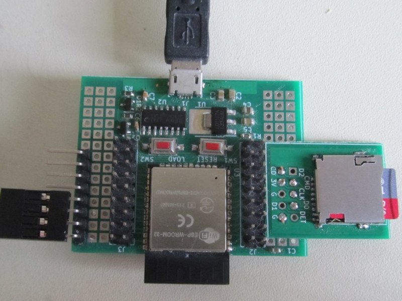
Ничего сложного или оригинального — с помощью готовой библиотеки в две строки запускается FTP сервер, используя который можно загрузить файлы на SD. Все BMP файлы форматом 32х32 последовательно отправляются к панелям — не знаю даже, что тут можно описывать, все просто, как грабли.
#include <Arduino.h>
#include <SPI.h>
#include <SD.h>
#include <WiFi.h>
#include <ESPmDNS.h>
#include <SimpleFTPServer.h>
#include "secrets.h"
#include <driver/spi_master.h>
#include "utils.h"


// ******************************************
// GPIO  5	SD Card CS (Chip Select)
// GPIO 18	SD Card MOSI (Master Out Slave In)
// GPIO 23	SD Card MISO (Master In Slave Out)
// GPIO 19	SD Card CLK (Clock)
// ******************************************
#define SD_CS   5
#define SD_MOSI 18
#define SD_MISO 23
#define SD_SCK  19

#define WIDTH 32
#define HEIGHT 32
#define PANEL_WIDTH 16
#define PANEL_HEIGHT 16
#define NUM_PANELS 4
#define IMAGE_CHANGE_INTERVAL 3000 // 10 seconds for changing images
#define SPI_PERIOD 500
#define SD_TEST_INTERVAL 5000

uint32_t originalData[WIDTH][HEIGHT];
uint32_t ledData[PANEL_WIDTH * PANEL_HEIGHT * NUM_PANELS];

#define PACKET_SIZE (PANEL_WIDTH * PANEL_HEIGHT * 3)
#define HSPI_BUFF_SIZE (PACKET_SIZE * NUM_PANELS)
#define PACKET_CNT NUM_PANELS
uint8_t hspi_data[HSPI_BUFF_SIZE];
uint8_t bmp_data[HSPI_BUFF_SIZE];
uint8_t *buff_ponter;
int16_t buff_counter;

#include "hspi.h"

FtpServer ftpServer;

uint32_t spi_time_now = 0;
volatile bool hspi_data_busy = false;


void spi_task(void *pvParameters)
{
  setup_hspi();
  spi_transaction_t t;
  while (true)
  {
    if (millis() >= spi_time_now + SPI_PERIOD)
    {
      hspi_data_busy = true;
      buff_ponter = hspi_data;
      buff_counter = PACKET_CNT;
      memset(&t, 0, sizeof(t));
      t.length = PACKET_SIZE * 8;
      t.tx_buffer = buff_ponter;
      spi_device_queue_trans(hspi, &t, portMAX_DELAY);
      buff_ponter += PACKET_SIZE;
      buff_counter--;
      spi_time_now += SPI_PERIOD;
    }

    if (dma_transfer_complete)
    {
      if (buff_counter > 0)
      {
        memset(&t, 0, sizeof(t));
        t.length = PACKET_SIZE * 8;
        t.tx_buffer = buff_ponter;
        spi_device_queue_trans(hspi, &t, portMAX_DELAY);
        buff_ponter += PACKET_SIZE;
        buff_counter--;
      }
      else hspi_data_busy = false;
      dma_transfer_complete = false;
    }
    yield();
  }
}


void ftp_server_task(void *pvParameters)
{
  while (true)
  {
    ftpServer.handleFTP();
    vTaskDelay(2);
  }
}

int remap_panels(int x, int y) {
  // Determine panel based on global coordinates
  int panel_x = x / PANEL_WIDTH; // 0 or 1
  int panel_y = y / PANEL_HEIGHT; // 0 or 1
  int panel = panel_y * 2 + panel_x; // Panel index: 0, 1, 2, 3

  // Local coordinates within the panel
  int local_x = x % PANEL_WIDTH;
  int local_y = y % PANEL_HEIGHT;

  // Determine destination panel and coordinates
  int dst_panel = panel;
  int dst_x = local_x;
  int dst_y = local_y;

  // For panels 2 and 3, swap positions and flip coordinates
  if (panel == 2) {
    dst_panel = 3; // Map panel 2 pixels to panel 3
    dst_x = (PANEL_WIDTH - 1) - local_x;
    dst_y = (PANEL_HEIGHT - 1) - local_y;
  } else if (panel == 3) {
    dst_panel = 2; // Map panel 3 pixels to panel 2
    dst_x = (PANEL_WIDTH - 1) - local_x;
    dst_y = (PANEL_HEIGHT - 1) - local_y;
  }

  // Compute index in bmp_data
  int panel_offset = dst_panel * PACKET_SIZE;
  int pixel_offset = (dst_y * PANEL_WIDTH + dst_x) * 3;
  return panel_offset + pixel_offset;
}

void fill_gradient_buffer()
{
  const uint8_t wave_table[16] = {0, 50, 100, 142, 181, 212, 231, 242, 231, 212, 181, 142, 100, 50, 0, 0};
  for (int y = 0; y < HEIGHT; y++)
  {
    for (int x = 0; x < WIDTH; x++)
    {
      uint8_t t = ((x + y) * 16) / (PANEL_WIDTH + PANEL_HEIGHT);
      uint8_t idx = t & 15;
      uint8_t r = wave_table[idx];
      uint8_t g = wave_table[(idx + 5) & 15];
      uint8_t b = wave_table[(idx + 10) & 15];
      int bmp_index = remap_panels(x, y);
      bmp_data[bmp_index + 0] = r;
      bmp_data[bmp_index + 1] = g;
      bmp_data[bmp_index + 2] = b;
    }
  }

  while (hspi_data_busy) vTaskDelay(1);
  memcpy(hspi_data, bmp_data, HSPI_BUFF_SIZE);
}

bool validate_bmp_file(File &bmpFile)
{
  uint8_t header[54];
  if (bmpFile.read(header, 54) != 54)
  {
    Serial.println("Invalid BMP header");
    return false;
  }
  if (header[0] != 'B' || header[1] != 'M' || *(uint16_t*)&header[28] != 24)
  {
    Serial.println("Unsupported BMP format (must be 24-bit)");
    return false;
  }
  int32_t width = *(int32_t*)&header[18];
  int32_t height = *(int32_t*)&header[22];
  if (width != WIDTH || height != HEIGHT)
  {
    Serial.printf("Invalid BMP dimensions: %dx%d, expected %dx%d\n", width, height, WIDTH, HEIGHT);
    return false;
  }
  return true;
}

bool load_bmp_to_buffer(const char* filename)
{
  File bmpFile = SD.open(filename);
  if (!bmpFile) {
    Serial.println("Failed to open BMP file");
    return false;
  }
  if (!validate_bmp_file(bmpFile))
  {
    bmpFile.close();
    return false;
  }
  uint8_t header[54];
  bmpFile.seek(0);
  if (bmpFile.read(header, 54) != 54)
  {
    Serial.println("Failed to re-read BMP header");
    bmpFile.close();
    return false;
  }
  uint32_t dataOffset = *(uint32_t*)&header[10];
  bmpFile.seek(dataOffset);

  // Read BMP pixels and write directly to bmp_data with remapping
  for (int y = 0; y < HEIGHT; y++)
  {
    int bmp_y = HEIGHT - 1 - y; // BMP is bottom-up
    for (int x = 0; x < WIDTH; x++) {
      uint8_t b = bmpFile.read();
      uint8_t g = bmpFile.read();
      uint8_t r = bmpFile.read();
      int bmp_index = remap_panels(x, bmp_y);
      bmp_data[bmp_index + 0] = r;
      bmp_data[bmp_index + 1] = g;
      bmp_data[bmp_index + 2] = b;
    }
  }
  bmpFile.close();

  while (hspi_data_busy) vTaskDelay(1);
  memcpy(hspi_data, bmp_data, HSPI_BUFF_SIZE);
  return true;
}

bool wifi_setup(void)
{
  WiFi.mode(WIFI_STA);
  WiFi.begin(ssid, password);
  delay(10);
  Serial.println();
  Serial.print("Waiting for WiFi... ");
  uint8_t i = 0;
  while ((WiFi.status() != WL_CONNECTED) && (i++ < 60))
  {
    Serial.print(".");
    delay(500);
  }
  if (i > 60)
  {
    Serial.print("\nCould not connect wifi");
    return false;
  }
  Serial.println("\nWiFi connected");
  Serial.print("IP address: ");
  Serial.println(WiFi.localIP());
  Serial.print("ESP32 HostName: ");
  Serial.println(WiFi.getHostname());
  Serial.print("RSSI: ");
  Serial.println(WiFi.RSSI());
  delay(500);
  if(!MDNS.begin("ftpesp32"))
  {
    Serial.println("Error starting mDNS");
    return false;
  }
  Serial.print("ESP32 HostName now: ");
  Serial.println(WiFi.getHostname());
  return true;
}
// ftpesp32.local


bool sd_available = true;
void setup()
{
  Serial.begin(115200);
  delay(100);
  Serial.println();
  Serial.println("ssh server test");
  fill_gradient_buffer();
  if (!sd_setup())
  {
    sd_available = false;
    Serial.println("Initial SD setup failed");
  }
  if(!wifi_setup()) ESP.restart();
  ftpServer.begin("root", "root");
  Serial.println("FTP server started!");
  xTaskCreatePinnedToCore(ftp_server_task, "FTP Server Task", 4096, NULL, 1, NULL, 0);
  xTaskCreatePinnedToCore(spi_task, "SPI Task", 4096, NULL, 1, NULL, 1);
}


uint64_t last_card_size = 0;
bool sd_setup(void)
{
  SPI.begin(SD_SCK, SD_MISO, SD_MOSI, SD_CS);
  if (!SD.begin(SD_CS))
  {
    Serial.println("Card Mount Failed");
    return false;
  }

  uint8_t cardType = SD.cardType();

  if (cardType == CARD_NONE)
  {
    Serial.println("No SD card attached");
    return false;
  }

  Serial.print("SD Card Type: ");
  if (cardType == CARD_MMC)       Serial.println("MMC");
  else if (cardType == CARD_SD)   Serial.println("SDSC");
  else if (cardType == CARD_SDHC) Serial.println("SDHC");
  else                            Serial.println("UNKNOWN");

  uint64_t cardSize = SD.cardSize() / (1024 * 1024);
  Serial.printf("SD Card Size: %llu MB\n", cardSize);
  last_card_size = cardSize; // Store initial card size
  return true;
}

void loop()
{
  static String current_file = "";
  static uint32_t last_sd_check = 0;
  static uint32_t last_image_change = 0;
  static uint32_t last_file_index = 0;

  // Check SD card size every SD_TEST_INTERVAL
  if (millis() - last_sd_check >= SD_TEST_INTERVAL)
  {
    uint64_t cardSize = SD.cardSize() / (1024 * 1024);
    if (cardSize != last_card_size)
    {
      Serial.println("SD card content changed, resetting file index");
      last_file_index = 0; // Reset index if card content changes
      last_card_size = cardSize;
      current_file = ""; // Force reload of new file
    }
    last_sd_check = millis();
  }

  // Load next image every IMAGE_CHANGE_INTERVAL or if no valid file is loaded
  if (millis() - last_image_change >= IMAGE_CHANGE_INTERVAL || current_file == "")
  {
    File root = SD.open("/");
    if (!root)
    {
      Serial.println("Failed to open SD root directory");
      fill_gradient_buffer(); // Fallback to gradient
      return;
    }

    bool found_valid_file = false;
    String next_file = "";
    uint32_t current_index = 0;

    // Try to find next valid BMP file
    while (File file = root.openNextFile())
    {
      if (!file.isDirectory())
      {
        String filename = file.name();
        if (current_index >= last_file_index)
        {
          File bmpFile = SD.open("/" + filename);
          if (bmpFile && validate_bmp_file(bmpFile))
          {
            next_file = "/" + filename;
            found_valid_file = true;
            bmpFile.close();
            last_file_index = current_index + 1;
            break;
          }
          bmpFile.close();
          current_index++;
        }
        else
        {
          current_index++;
        }
      }
      file.close();
    }
    root.close();

    // If no file found at current index, try from beginning
    if (!found_valid_file)
    {
      last_file_index = 0;
      root = SD.open("/");
      if (!root)
      {
        Serial.println("Failed to open SD root directory");
        fill_gradient_buffer(); // Fallback to gradient
        return;
      }
      current_index = 0;
      while (File file = root.openNextFile())
      {
        if (!file.isDirectory())
        {
          String filename = file.name();
          File bmpFile = SD.open("/" + filename);
          if (bmpFile && validate_bmp_file(bmpFile))
          {
            next_file = "/" + filename;
            found_valid_file = true;
            bmpFile.close();
            last_file_index = current_index + 1;
            break;
          }
          bmpFile.close();
          current_index++;
        }
        file.close();
      }
      root.close();
    }

    if (found_valid_file)
    {
      current_file = next_file;
      Serial.println("Loading BMP: " + current_file);
      if (load_bmp_to_buffer(current_file.c_str()))
      {
        last_image_change = millis();
      }
      else
      {
        Serial.println("Failed to load BMP, trying next file");
        last_file_index++;
        current_file = "";
      }
    }
    else
    {
      Serial.println("No valid BMP files found");
      last_file_index = 0;
      last_image_change = millis();
      current_file = "";
      fill_gradient_buffer(); // Fallback to gradient
    }
  }

  yield();
  delay(100);
}#ifndef _hspi_h
#define _hspi_h
// *************************************
// SPI MOSI MISO CLK CS
// HSPI GPIO13 GPIO12 GPIO14 GPIO15
// ++++++++++++++++++++++++++++++++++++++
// Configuration parameters for HSPI
#define HSPI_MISO 12
#define HSPI_MOSI 13
#define HSPI_SCLK 14
#define HSPI_CS 15
#define CLOCK_SPEED_HZ 12000000 // 12 MHz
spi_device_handle_t hspi;
// SPI DMA Transfer Complete Flag
volatile bool dma_transfer_complete = false;
void IRAM_ATTR spi_dma_complete_isr(spi_transaction_t *trans)
{
dma_transfer_complete = true;
}
int fInitializeSPI_Devices(spi_device_handle_t &h, int csPin)
{
esp_err_t intError;
spi_device_interface_config_t dev_config = { }; // Initializes all fields to 0
dev_config.address_bits = 0;
dev_config.command_bits = 0;
dev_config.dummy_bits = 0;
//dev_config.mode = 3; // For DMA, only 1 or 3 is available
dev_config.mode = 1; // For DMA, only 1 or 3 is available
dev_config.duty_cycle_pos = 0;
//dev_config.cs_ena_posttrans = 0;
//dev_config.cs_ena_pretrans = 0;
dev_config.cs_ena_posttrans = 1; // Delay after transmission
dev_config.cs_ena_pretrans = 1; // Delay before transmission
dev_config.clock_speed_hz = CLOCK_SPEED_HZ;
dev_config.spics_io_num = csPin;
dev_config.flags = 0;
dev_config.queue_size = 1;
dev_config.pre_cb = NULL;
//dev_config.post_cb = NULL;
dev_config.post_cb = spi_dma_complete_isr; // Set the post callback to ISR
intError = spi_bus_add_device(HSPI_HOST, &dev_config, &h);
return intError;
}
int fInitializeSPI_Channel(int spiCLK, int spiMOSI, int spiMISO, spi_host_device_t SPI_Host, bool EnableDMA)
{
esp_err_t intError;
spi_bus_config_t bus_config = { };
bus_config.sclk_io_num = spiCLK; // CLK
bus_config.mosi_io_num = spiMOSI; // MOSI
bus_config.miso_io_num = spiMISO; // MISO
bus_config.quadwp_io_num = -1; // Not used
bus_config.quadhd_io_num = -1; // Not used
intError = spi_bus_initialize(SPI_Host, &bus_config, EnableDMA ? 1 : 0);
return intError;
}
void setup_hspi()
{
if (fInitializeSPI_Channel(HSPI_SCLK, HSPI_MOSI, HSPI_MISO, HSPI_HOST, true) != ESP_OK)
{
Serial.println("Failed to initialize SPI channel");
while (1);
}
if (fInitializeSPI_Devices(hspi, HSPI_CS) != ESP_OK)
{
Serial.println("Failed to initialize SPI device");
while (1);
}
Serial.println("HSPI and DMA setup complete");
}
#endif
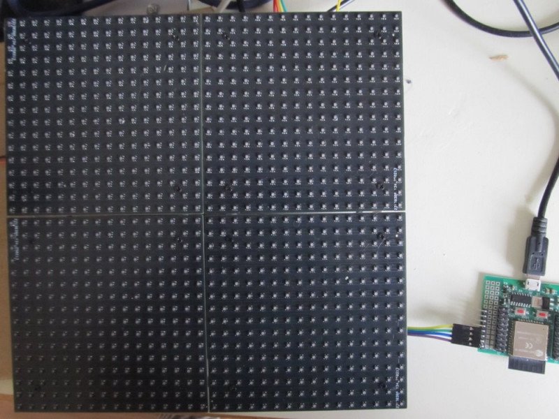
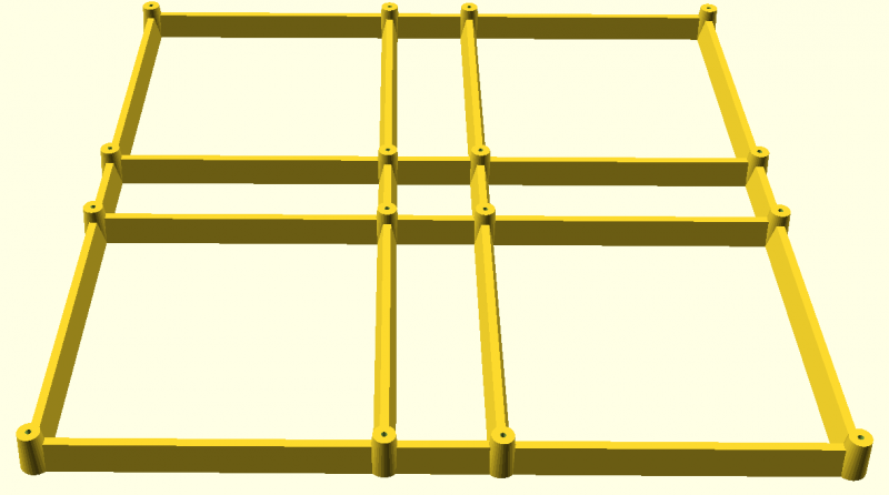
Панели скреплены друг с другом напечатанной на 3D принтере решеткой. Решетка разработана в OpenSCAD. Почему именно OpenSCAD? Во-первых, потому что это многих очень раздражает. Во-вторых, ИИ уже научился рисовать на нем, чем я и воспользовался. Не потому, что надо — сам бы я это сделал в несколько раз быстрее. Но интересно же.
board_size = 100;
hole_spacing = 75;
main_cylinder_base_d = 7;
main_cylinder_top_d = 5;
main_cylinder_h = 10;
perimeter_cylinder_base_d = 5;
perimeter_cylinder_top_d = 2;
perimeter_cylinder_h = 7;
board_spacing = 0;
module single_board() {
hole_positions = [
[hole_spacing/2, hole_spacing/2],
[hole_spacing/2, -hole_spacing/2],
[-hole_spacing/2, hole_spacing/2],
[-hole_spacing/2, -hole_spacing/2]
];
for (pos = hole_positions) {
translate([pos[0], pos[1], 0])
cylinder(h = main_cylinder_h, d1 = main_cylinder_base_d, d2 = main_cylinder_top_d, $fn=32);
}
}
module perimeter_frame() {
frame_positions = [
[-hole_spacing/2, board_size + board_spacing + hole_spacing/2],
[board_size + board_spacing + hole_spacing/2, board_size + board_spacing + hole_spacing/2],
[board_size + board_spacing + hole_spacing/2, -hole_spacing/2],
[-hole_spacing/2, -hole_spacing/2]
];
for (i = [0:3]) {
hull() {
translate(frame_positions[i])
cylinder(h = perimeter_cylinder_h, d1 = perimeter_cylinder_base_d, d2 = perimeter_cylinder_top_d, $fn=32);
translate(frame_positions[(i+1)%4])
cylinder(h = perimeter_cylinder_h, d1 = perimeter_cylinder_base_d, d2 = perimeter_cylinder_top_d, $fn=32);
}
}
}
module perimeter_connectors() {
horizontal_connector_positions = [
[-hole_spacing/2, hole_spacing/2],
[board_size + board_spacing + hole_spacing/2, hole_spacing/2],
[-hole_spacing/2, board_size + board_spacing - hole_spacing/2],
[board_size + board_spacing + hole_spacing/2, board_size + board_spacing - hole_spacing/2]
];
vertical_connector_positions = [
[hole_spacing/2, board_size + board_spacing + hole_spacing/2],
[hole_spacing/2, -hole_spacing/2],
[board_size + board_spacing - hole_spacing/2, board_size + board_spacing + hole_spacing/2],
[board_size + board_spacing - hole_spacing/2, -hole_spacing/2]
];
hull() {
translate(horizontal_connector_positions[0])
cylinder(h = perimeter_cylinder_h, d1 = perimeter_cylinder_base_d, d2 = perimeter_cylinder_top_d, $fn=32);
translate(horizontal_connector_positions[1])
cylinder(h = perimeter_cylinder_h, d1 = perimeter_cylinder_base_d, d2 = perimeter_cylinder_top_d, $fn=32);
}
hull() {
translate(horizontal_connector_positions[2])
cylinder(h = perimeter_cylinder_h, d1 = perimeter_cylinder_base_d, d2 = perimeter_cylinder_top_d, $fn=32);
translate(horizontal_connector_positions[3])
cylinder(h = perimeter_cylinder_h, d1 = perimeter_cylinder_base_d, d2 = perimeter_cylinder_top_d, $fn=32);
}
hull() {
translate(vertical_connector_positions[0])
cylinder(h = perimeter_cylinder_h, d1 = perimeter_cylinder_base_d, d2 = perimeter_cylinder_top_d, $fn=32);
translate(vertical_connector_positions[1])
cylinder(h = perimeter_cylinder_h, d1 = perimeter_cylinder_base_d, d2 = perimeter_cylinder_top_d, $fn=32);
}
hull() {
translate(vertical_connector_positions[2])
cylinder(h = perimeter_cylinder_h, d1 = perimeter_cylinder_base_d, d2 = perimeter_cylinder_top_d, $fn=32);
translate(vertical_connector_positions[3])
cylinder(h = perimeter_cylinder_h, d1 = perimeter_cylinder_base_d, d2 = perimeter_cylinder_top_d, $fn=32);
}
}
module single_board_holes() {
hole_positions = [
[hole_spacing/2, hole_spacing/2],
[hole_spacing/2, -hole_spacing/2],
[-hole_spacing/2, hole_spacing/2],
[-hole_spacing/2, -hole_spacing/2]
];
for (pos = hole_positions) {
translate([pos[0], pos[1], 0])
cylinder(h = 20, d = 1.3, $fn=32);
}
}
difference() {
union() {
for (i = [0:1]) {
for (j = [0:1]) {
translate([(board_size + board_spacing) * i,
(board_size + board_spacing) * j,
0])
single_board();
}
}
perimeter_frame();
perimeter_connectors();
}
translate([0,0,-2]) {
for (i = [0:1]) {
for (j = [0:1]) {
translate([(board_size + board_spacing) * i,
(board_size + board_spacing) * j,
0])
single_board_holes();
}
}
}
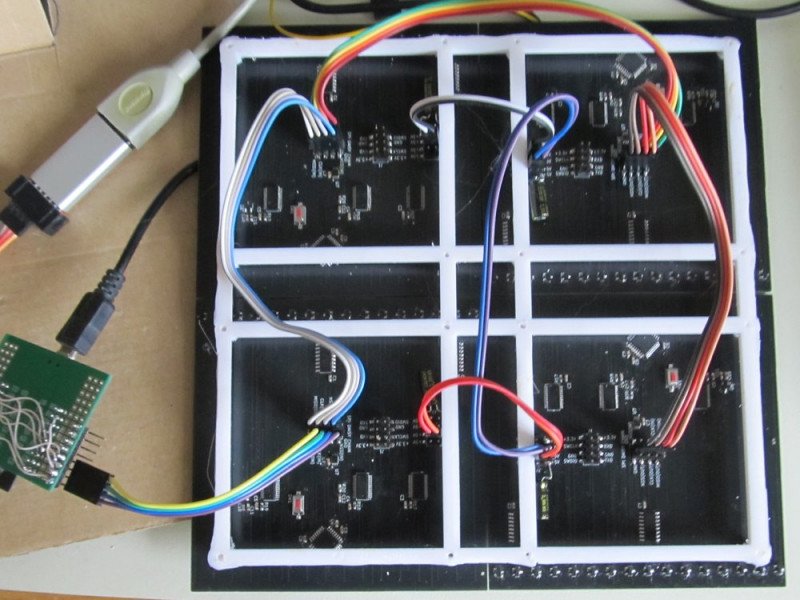
}После долгих объяснялок Grok нарисовал что-то очень близкое к тому, что мне было надо. Потом терпение лопнуло, я доделал до конца ручками и поставил печатать. С первым экземплярам обломился — Grok сделал зазор между платами, а я не обратил внимания. Но после поправки одной цифры второй экземпляр получился таким, как я планировал.
Ну и что мы имеем в итоге:

Только не спрашивайте, зачем я все это сделал и кому это надо…
А вот статью написать — это точно полезно. Когда на своем компьютере что-то потеряешь или случайно сотрешь, идешь на Mysku — и вот оно, в целости-сохранности. Да еще и с пояснениями, которые для себя поленишься делать.
P.S. Я извиняюсь, комментариями в исходниках пришлось пожертвовать — иначе статья в допустимый лимит знаков не укладывалась.
| +27 |
1468
27
|
| +36 |
1219
36
|
| +41 |
2646
44
|
| +55 |
1851
37
|
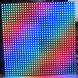
Кто в начале 80-х не делал цветомузыки, тот не поймёт. Сюда же ещё DSP какую-то нужно, и будет лучше, чем, в свою бытность, визуализация в Винампе!
Заглавная фотка именно это и иллюстрирует.
PS: С большим удовольствием поставил плюс. Спасибо за ваши статьи!
(всё не влезло, остальное по ссылке)
Но комментарии, когда нет тонких мест, вполне разумны, можно не напрягаться комментированием мелочей, поручить все ИИ.
Что порождает кучу совсем других проблем: например, меня с 20+ лет опыта в моей отрасли ИИ не заменит, но вот рабочие места для молодых спецов уже второй год как идут под нож. Если раньше «юным падаванам» давали набить шишек на простых задачках, то теперь можно достичь охрененной краткосрочной экономии, перепоручив этот класс задач машине. На чём молодняк будет учиться завтра — решительно непонятно, как они будут зарабатывать на кусок хлеба — тоже.
Я как-то заказал, но пришли с какой-то адовой яркостью красного, под которую вытянуть синий и зеленый до белого было никак. Красный надо было душить наверное на 2 порядка по току, чтобы там что-то можно было регулировать в оттенках…
Ну и у вас светодиоды может с Али были? — там часто продают бины, которые в производство никто не берет.
Скорее всего выставлял, но результатов не помню. Лет 5 назад было.
Но чем бы дитя не тешилось…
Классические панели с HUB75 — это тупая куча сдвиговых регистров + дешифраторы с ключами и всё. А всё сканирование идёт внешним контроллером.
Вы по сути перенесли кусок контроллера, который занимается сканированием, в панель и в мастере осталась только функция раздачи данных картинки.
Можно так сделать? Можно. И что-то подобное даже делается в «больших» видео панелях. Только там сами панели по прежнему «тупые», но добавляется слой receiving cards, которые принимают данные от мастера и управляют неким количеством панелей. Но там всё на FPGA, конечно.
Вообще, идея работы с LED панелями как с обычным LCD/OLED индикатором давно витает в воздухе. Цены на LED панели на ALI уже давно копеечные, а возможности огромные. Но всё упирается в этот самый HUB75 — чтобы с достаточной скоростью дергать ножками нужно ставить «жирный» контроллер, который только этим и будет занят по сути.
Я n лет назад пытался обойти эту проблему маленькой платкой с CPLD и FIFO памятью, но решение оказалось откровенно неудачным, хотя и рабочим.
Идеальным вариантом была бы какая-то платка, которая бы втыкалась в HUB75, брала бы на себя все функции хранения изображения и работы с панелью и имела внешний интерфейс I2C или SPI. У меня была идея реализовать это на какой-нибудь недорогой FPGA, но руки так и не дошли.
Может быть, кстати, что-то подобное уже и реализовано — давно не интересовался, честно говоря.
А теперь к проекту — самое интересное вы и не рассказали. Каким образом, в итоге, осуществляется регулировка яркости свечения? PWM 16 бит? На какой частоте? Почему надо, чтобы DMA непосредственно в порт выводило? Какой объем выводится за раз? Когда это рассчитывается?
Яркость свечения делает ICND2153, как это делается — хорошо описано в спецификации на STP1612PW05. Принцип тот же, но детали могут быть разные, документации на ICND2153 нет. Частота определяется GKCL, у меня она генерируется TIM3 — 64/5=12.8мHz, учитывая разгон процессора. DMA — Все необходимые сигналы генерируются им, готовится сигнатура в памяти и потом выплевывается за раз.
Запихав файлы в Grok получил детальнейшее описание, больше моей статьи. Пришлось его просить урезать осетра:
Программно же у вас сделана динамическая индикация 16:1, процессор перебирает ряды и грузит нужные данные в ICND2153. И это происходит с частотой 2400 Гц, то есть, «экран» мигает с частотой 2400/16 = 150 Гц.
А зачем вам вообще тогда DMA? Почему бы не дергать пины просто из кода? В году 19-м или 20-м я хотел сделать себе большой анализатор спектра, для него собирал «экран» из светодиодных полосочек размером 24х40х2 с простыми СС-драйверами на 16 бит. Схемотехнически, кстати, проект был похож на ваш — каждый столбик управлялся своим p-channel mosfet, подключенным к 595-му регистру. Только динамическая индикация у меня была 12:1, и для снижения нагрузки на СС-драйвер, из 16-ти бит я использовал только 10 (но передавать приходилось 16). Частота смены столбцов была, кажется, 3200 Гц, то есть, частота мигания экрана 267 Гц.
Итого, мой экран занимал 64х12х4 = 3072 бит или 819200 бит в секунду. Как помню, код динамической индикации занимал примерно 3-5% времени обычного 72-МГц STMF103. У вас экран занимает 16х16х16х3 = 12288 бит или 1843200 бит в секунду, то есть, всего в 2.25 раза больше моего. Зачем тут что-то изобретать с DMA?
А вот так выглядит кусок кода, осуществляющего вывод:
В свое время при изготовлении похожего устройства столкнулся с перегревом диодов по центру платы. У меня правда плотность диодов была выше. Пришлось делать многослойную плату, с отводом тепла на обратную сторону, убирать оттуда трассировку и приделывать радиаторы…
Кстати, jlcpcb делают многослойки не сильно дороже двухслойных плат, только у них ограничения по материалам и стеку.
В смысле, думал что на каждый модуль будет по одному стму, а от него уже все остальное на модуле управляется — тогда SPI для связи модулей вроде как за глаза.
МОЛОДЕЦ!
и здоровья
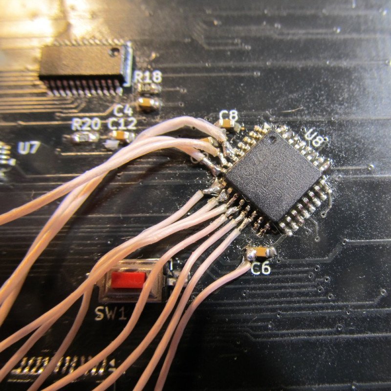
Я вот так распаять проводочки к TQFP и без инвалидности вряд ли смогу :)